How to Install a Pre Cleaner on Construction Machinery

Time:2026-09-30 Author:Oliver
0%

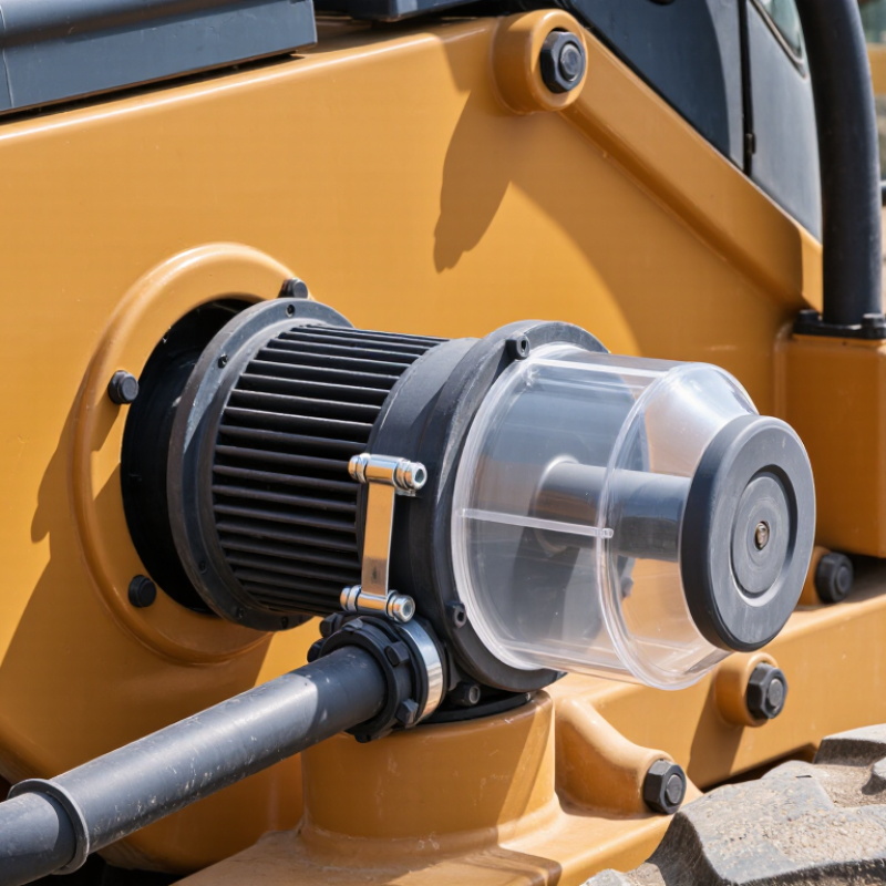
A pre-cleaner is a small component with a demanding job: it spins dust and debris away before air reaches the engine’s main filter. On a dry construction site, that can mean less packed dust around the filter pleats and fewer interruptions for inspection. Still, a pre-cleaner is not a substitute for scheduled filter maintenance.

The U.S. Environmental Protection Agency’s nonroad-engine materials identify construction equipment as a source of particulate emissions, underscoring why clean intake air and sound engine maintenance matter. For installation, the practical details are just as important: confirm the pre-cleaner fits the machine’s intake, check airflow direction, secure the connections, and keep the assembly clear of nearby panels or exhaust heat. A clamp that feels tight by hand may still loosen under vibration.

This guide explains how to install a pre-cleaner on construction machinery, from checking compatibility to inspecting the finished fit. Follow the machine and pre-cleaner manufacturers’ instructions, since mounting methods and service limits vary. One caution: no verifiable, topic-specific quotation from a named installation expert was supplied for this introduction, so none is attributed here. That gap matters; a confident-sounding quote should never replace a service manual.
How to Install a Pre Cleaner on Construction Machinery

Match the Pre-Cleaner’s Rated Airflow to the Engine’s OEM CFM Requirement

How to Install a Pre-Cleaner on Construction Machinery

Before installation, find the engine’s OEM air requirement in cubic feet per minute (CFM). Use the maximum airflow demand at full load, not the machine’s idle rate. The pre-cleaner’s rated airflow should meet or slightly exceed this figure. A lower rating can restrict intake air, reduce power, and increase fuel consumption.

Excessive oversizing is not always better. It may create poor separation efficiency or fit poorly on the intake stack. Check the rating conditions, including pressure drop and operating speed.

Inspect the intake pipe, clamp, and sealing surface before fitting the unit. Clean away dust and rust. Install the pre-cleaner vertically, with enough clearance for debris discharge and routine inspection. Keep it away from exhaust heat and moving linkages.

After tightening the clamp, run the engine under load and check for unusual intake noise, smoke, or power loss. A restriction gauge gives better evidence than sound alone.

On one installation, I focused too much on pipe diameter and nearly missed the engine’s peak CFM requirement. That was a useful mistake.

Recheck the calculation for high-altitude work, heavy dust, and continuous operation. If the machine works in severe conditions, leave access for frequent cleaning and inspect the filter after the first several operating hours.

Overlooking that first inspection can hide a loose seal or an incorrectly seated pre-cleaner.

Compare Dust-Separation and Restriction Data Using ISO 5011:2014

How to Install a Pre Cleaner on Construction Machinery

Compare Dust-Separation and Restriction Data Using ISO 5011:2014

Install the pre cleaner upstream of the main air cleaner, with the outlet facing away from exhaust heat and direct rain. Check the intake pipe for cracks, then secure each clamp without deforming the tube. Keep the pre cleaner vertical when its design requires gravity-assisted dust discharge. A slight misalignment can create leaks and distort test results. It happens more often than expected.

ISO 5011:2014 provides a controlled method for evaluating air-cleaner performance. Compare dust-separation efficiency with intake restriction under the same airflow and test-dust conditions. Record pressure before and after the pre cleaner, using calibrated instruments. A good result removes substantial dust while adding limited restriction. However, laboratory figures may not represent loose soil, wet clay, or vibration on a working machine. I would repeat the test after installation, because installation quality can change the outcome.

Tips: Photograph the original intake layout before modification. Mark airflow direction clearly. Inspect the dust outlet after every shift in severe dust. Check clamps and seals when restriction rises unexpectedly. Do not judge performance by appearance alone. A cleaner-looking bowl may still indicate poor separation. Keep test records with engine speed, airflow, dust mass, and restriction readings. Small recording errors can weaken an otherwise useful comparison.

How to Install a Pre Cleaner on Construction Machinery

ISO 5011:2014-style comparison of dust-separation efficiency and intake restriction at increasing airflow rates.

The test series shows the typical relationship between airflow, dust separation, and restriction. Higher airflow increases intake restriction, while separation efficiency may decline slightly as the air velocity through the pre-cleaner increases. Final installation decisions should be based on measured ISO 5011 test results for the selected machinery and operating conditions.

Choose a Mounting Position Clear of Exhaust Heat and Dust Plumes

Before mounting a pre-cleaner, watch the machine working through a full cycle. A position that looks clear while parked may sit directly in a dust plume when the loader turns or the excavator swings. Check where the exhaust flows, too. Heat can damage nearby seals, while exhaust gases and oily residue may be drawn toward the air intake.

Keep the pre-cleaner away from hot exhaust parts and out of the path of dust thrown up by tires, tracks, buckets, or nearby equipment. Even a brief cloud can load the intake with fine grit. Look for a location with steady, relatively clean airflow and enough room to remove the bowl for servicing. Measure the clearance with the hood open and closed. Check the machine’s service guidance before drilling or welding; nearby panels may hide wiring or structural members.

A short field test helps. Run the machine in its usual work area, then inspect the mounting point and intake after several passes. Look for fresh dust streaks, heat discoloration, or loosened hardware. A clean-looking spot is not proof. Dust shifts with wind and attachment movement, and I would recheck the location after the first work shift. Secure the bracket against vibration, but avoid placing it where routine maintenance becomes awkward.

Secure the Pre-Cleaner and Seal Joints to the Manufacturer’s Specifications

After installing a pre-cleaner, secure it firmly and seal every joint to the manufacturer’s specifications. A loose housing can admit unfiltered dust before it reaches the main air filter. I have seen clamps loosen after repeated vibration, especially on rough haul roads. Check the inlet tube, mounting bracket, clamp tension, and drain valve before starting the engine. The joint should remain aligned, without stress or visible gaps.

Use the torque value, sealant type, and tightening sequence specified for the machine. Do not guess. ISO 5011:2016 evaluates air-cleaner performance through dust-separation efficiency and pressure-loss testing. SAE J726 also supports restriction testing for heavy-duty air-cleaner systems. These standards show why a poorly sealed connection can distort airflow readings and reduce filtration performance. After installation, inspect the seal while the engine idles. A faint whistle may indicate leakage, but noise alone is not a reliable test. A smoke test or controlled pressure check is better when available.

Tips: Clean both mating surfaces first. Use a calibrated torque tool. Mark the clamp position with a paint line. Recheck it after the first operating shift. I once treated a small gap as harmless. It was not. Also record restriction readings before and after installation. That simple record helps identify dust loading, installation errors, or an unsuitable pre-cleaner. Keep the inspection practical and repeatable.

Check Intake Restriction Against the OEM Limit After Installation

Installing a pre-cleaner on construction machinery is more than securing a bowl above the intake. The unit must sit upright, clear nearby structures, and match the intake pipe diameter. Check the airflow arrow, if provided. Tighten clamps evenly, then inspect every joint for dust paths or crushed hoses. A clean-looking installation can still fail this check.

After installation, measure intake restriction against the engine manufacturer’s OEM limit. Do not guess. Use a calibrated manometer or approved diagnostic gauge at the specified test point. The most useful reading usually comes with the engine warm and operating near rated speed and load, not at idle. Record the value before and after fitting the pre-cleaner. This creates practical evidence, not a workshop opinion.

If restriction exceeds the OEM limit, stop operating under heavy load and investigate. Check for a blocked pre-cleaner screen, an undersized adapter, a collapsed hose, or a filter loaded with dust. Confirm that the pre-cleaner is not installed backward or too close to an exhaust outlet. I have seen technicians tighten every clamp and still miss a partially closed intake flap. Small errors matter. Repeat the measurement after correction, using the same engine condition and gauge position. Keep the readings with the machine’s service records, including temperature, engine speed, and observed load. The first reading may be imperfect, especially when load control is inconsistent. Recheck it.

FAQS

Where should a pre-cleaner be installed?

Install it upstream of the main air cleaner. Keep the outlet away from exhaust heat and direct rain. Follow the unit’s design if it needs to stay vertical. Small angles matter.

How can I choose a suitable mounting position?

Watch the machine complete a normal work cycle. Avoid dust from tires, tracks, buckets, and nearby equipment. Check the spot with the hood both open and closed. A parked machine can fool you.

How should dust-separation and restriction performance be compared?

Compare both measurements under the same airflow and test-dust conditions. Use calibrated instruments to record pressure before and after the pre-cleaner. Keep the test conditions consistent. Otherwise, the comparison may be weak.

What does a useful test result look like?

It removes substantial dust while adding limited intake restriction. There is no single result here that fits every machine. Laboratory figures may differ from wet clay, loose soil, or vibration in the field.

Can installation affect test results?

Yes. A cracked pipe, loose clamp, or slight misalignment can create an air leak. That can distort the readings. I would repeat the test after installation, even when the first result looks convincing.

What should operators inspect during routine work?

In severe dust, inspect the dust outlet after every shift. Check clamps and seals if restriction rises unexpectedly. Look for fresh dust streaks, heat discoloration, or loosened hardware. Appearance alone is not enough.

What details should be recorded during testing?

Record engine speed, airflow, dust mass, and restriction readings. Photograph the original intake layout and mark airflow direction. Small recording errors can weaken an otherwise useful comparison.

How can the mounting point be checked after installation?

Run the machine through several passes in its usual work area. Then inspect the intake and bracket for dust, heat marks, or movement. Recheck after the first shift. Dust does not always behave as expected.

Conclusion

Learning how to install a pre-cleaner on construction machinery starts with matching its rated airflow to the engine’s original equipment manufacturer (OEM) CFM requirement. A unit that is poorly matched may restrict incoming air or separate dust less effectively. Before installation, compare available dust-separation and restriction data measured under ISO 5011:2014 conditions, so the selection reflects both filtration performance and airflow needs.

Choose a mounting position that avoids exhaust heat, moving components, and dust plumes that could send debris back toward the intake. Secure the pre-cleaner and seal all joints according to the manufacturer’s specifications, checking that the assembly is stable and connections are airtight. After installation, measure intake restriction under the appropriate operating conditions and compare the result with the engine’s OEM limit. If restriction exceeds that limit, inspect the installation and airflow path before returning the machine to regular service.

Oliver

Oliver

Oliver is a seasoned marketing professional with a wealth of expertise in driving brand awareness and engagement. With a deep understanding of our company's product offerings, he consistently delivers high-quality content that enriches our professional blog. His insights not only shed light on......